
⌄
3-Phase Variable Frequency Drive (VFD)
Results at a glance
1 Hz – 3,800 Hz
PWM Sine-Wave Generated
1 Hz – 140 Hz (3-phase BLDC)
3-Phase BLDC Motor Control
Designed in EasyEDA + manufactured in China under tight deadline
Custom PCB Delivered
Circuit, firmware, soldering, and PCB
Full System Built Solo
Overview
During my Power Electronics course, I designed and built a complete 3-phase Variable Frequency Drive entirely on my own. The system was controlled by a PIC16F18876 microcontroller, for which I wrote all firmware from scratch using only the datasheet — no libraries, application notes or simulation model existed for this part.
I implemented sine-wave modulated PWM with a 84-point lookup table, achieving a frequency range from 1 Hz to 3,800 Hz. The VFD successfully drove a 3-phase BLDC motor from 1 Hz up to 140 Hz.
Starting on a protoboard, I later designed a custom PCB in EasyEDA (learning the tool along the way under deadline pressure), had it manufactured in China, and assembled the final board with IGBTs, photocouplers, BJTs, and a 4-digit 7-segment display. The circuit featured push-button speed control and an array of LEDs that visually displayed the real-time PWM switching on the IGBT gates — an outstanding debugging and demonstration tool.


Development Process

1
Oscilloscope verification
Confirmed correct sine-wave generation by checking PWM duty cycle from 0% (bottom) to 100% (top) using the 42-point lookup table.

5
Creative LED debugging
Added real-time PWM visualization LEDs to every output pin — the only way to debug 6 signals at 1 Hz without an oscilloscope at home.
9
Quick functional test
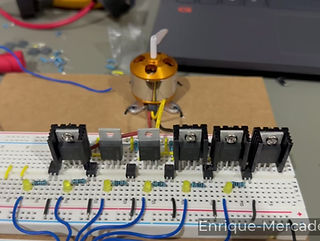
Ran a successful high-speed motor test without heatsinks on two IGBTs — late-night “nothing ventured, nothing gained” validation.

13
Protoboard before cannibalization
Final photo of the fully working protoboard version before transferring components to the new PCB.
17
Initial PCB troubleshooting
Discovered voltage source protection tripping due to lower resistance on the PCB vs protoboard.
2
Half-sine wave output
Verified one PWM channel producing only the positive half of the sine wave for a single IGBT driver.
6
LED sine-wave visualization
Slow-motion phone video clearly showing the three phase-shifted sine waves at 1 Hz through the LED array.
10
7-Segment RPM display
Added real-time frequency display and achieved smooth motor control with push-button interface.

14
PCB assembly begins
Started soldering components onto the freshly arrived manufactured board.
18
Final successful run
Full system working perfectly — smooth motor control from 2 Hz to 150 Hz using the new button interface on the finished PCB.

3
Full sine-wave output
Captured the complete reconstructed sine wave and PWM switching on the oscilloscope.
7
First motor spin-up
Successfully drove the 3-phase BLDC motor for the first time — firmware changed manually via PIC programmer.

11
PCB design in EasyEDA
Learned EasyEDA on the spot under tight deadline and completed the full THT layout in record time.

15
Mid-assembly
Progress shot with most components in place and wiring underway.

4
Dual PWM outputs
Validated both half-sine waves on separate channels using the only available PIC18F4550 and two-channel oscilloscope.
8
Button interface added
Implemented speed-up, speed-down, and power buttons while refining the protoboard layout.

12
Finished PCB layout
Final design ready — sent to China for express manufacturing to meet the project deadline.

16
Fully assembled PCB
Complete custom PCB with motor connected — ready for final testing.


Technical Deep Dive
Project Goals & Design Constraints
Project Goals & Design Constraints
The professor for my Power Electronics class gave us a broad objective of building a 3-Phase Variable Frequency Drive as the class final project, the only instructions and constraints were the following:
-
Three weeks deadline.
-
The power input was a 12VAC source which had to be rectified in the process.
-
The output had to be a 3-phase PWM-Sine wave without distortion.
-
The output had to drive a 3-phase BLDC motor.
-
The output frequency had to be adjustable.
I decided not to take the easy route, and my own goals were to:
-
Drive a 3-phase AC motor.
-
Ensure the high resolution of the output sine waves.
-
Making the electric circuit as tidy and small as possible.
-
Using a PIC microcontroller to drive the whole project.
-
Use IGBTs for the learning experience and to drive the AC motor.
-
Delivering the working project in a professionally manufactured and assembled PCB.
System Architecture Overview
System Architecture Overview
The VFD is built around two tightly coupled parts: a control stage and a power stage.
The control stage is a PIC16F18876 microcontroller running bare-metal firmware. It generates three synchronized sine-wave PWM signals, reads three push-buttons for frequency and run/stop control, and drives a 4-digit 7-segment display to show the current output frequency.
The power stage is a classic three-phase inverter made with six 650 V IGBTs. Each IGBT has its own aluminum heatsink. Optical isolation separates the low-voltage logic from the power side, and flyback diodes protect against inductive spikes.
The whole system converts 12 V DC into a variable-frequency three-phase output that can smoothly drive the motor from a slow crawl up to 140 Hz in testing, with a theoretical maximum of 3800 Hz.
A set of six LEDs (one pair per phase) wired in series with the optocouplers gives beautiful real-time visual feedback of the three phases rotating — something I originally built for debugging but ended up keeping because it looks surprisingly good when the drive is running.

Firmware Deep Dive
Firmware Deep Dive
All the firmware was written from scratch in C. I kept the code modular, readable, and heavily commented; according to the best practices.
The heart of the system is a single Timer0 interrupt whose period is not fixed. Every time you press the frequency up or down button, a function recalculates and changes the Timer0 registers. This changes the time between interrupts, which directly controls how quickly the PWM duty cycle steps through the sine lookup table, and therefore sets the output frequency.

I used a 42-point sine lookup table for each phase. When any index reaches 42, the firmware toggles a direction flag for that phase and instantly remaps the PPS (Peripheral Pin Select) pins. This swaps the high-side and low-side drive signals on the fly. Effectively, the 42-point table behaves like an 84-point table without doubling memory usage or interrupt load.
The choice of 42 points was a deliberate compromise. A larger table would give a smoother sine wave, but it would force the interrupt to fire more often. At high output frequencies that would mean the next duty-cycle update arrives before the previous PWM cycle even finishes — breaking the waveform. A smaller table would allow even higher frequencies, but the output would start looking stepped and ugly. 42/84 gave me the best balance between waveform quality and maximum reachable frequency (3800 Hz).
Three button interrupts (on-change) handle frequency increase, decrease (with auto-stop when reaching 0), and run/stop. When stopping, all duty cycles are instantly zeroed and the frequency resets to a safe 10 Hz to effectively start momentum when restarting the motor.
As the control logic for the output frequency runs on the interrupt function, the Main code is practically free and available to do any other function. In this case, the only thing that is taking place constantly is the update of the multiplexed 7-segment display.
As a fun fact, because I couldn’t always access the university oscilloscope, the fact that it had only two channels, and because I usually worked late at night at home; I came up with a simple but effective debugging method: six LEDs, one pair per phase, wired in series with the optocoupler inputs. At 1 Hz you can watch the “rotation” with your eyes. I used slow-motion video on my phone for faster speeds. The LEDs also helped me catch a phase-shift mistake (the three phases were not exactly 120° apart). I liked the visual feedback so much that I left them in the final circuit. When the VFD runs, you can see the three phases speeding up and slowing down.
All my code developed for this project, the project files, and the programming files are available at the end of the page and on my linked GitHub.

Main Function Code Snippet
Hardware & Power Electronics Deep Dive
Hardware & Power Electronics Deep Dive
I chose to do the project with IGBTs mainly for the learning experience. I chose the IGP30N65H5 because most IGBTs require a higher gate-emitter voltage, but these switch cleanly with a typical 4 V, great for ensuring activation with the 12V source; and because they are rated for 55 A - 650 V, as my intention was to drive a small AC motor if the opportunity came to be.
I used optocouplers for full galvanic isolation between the logic and power stages, plus isolation slots on the PCB. Each IGBT has its own aluminum heatsink bolted on. Flyback diodes rated for the output voltage protect against inductive kickback.
On the PCB layout I made the high-current traces visibly thicker than the logic traces and routed them with 45-degree angles and minimal turns to keep things clean and reduce inductance. I didn’t do advanced thermal simulations or noise isolation analysis at the time, as I kept it practical and effective for a student project.
One detail I only learned later is that I should have added a small series gate resistor on each IGBT. I did include pull-down resistors so the gates wouldn’t float, and the board works reliably without them, but in a commercial product that gate resistor would be essential to control switching speed and prevent ringing.
The entire Circuit Board was designed, laid out in EasyEDA, fabricated at JLCPCB, and hand-soldered by me in one intense all-nighter.
.webp)
Complete Circuit Schematic
Challenges, Trade-offs & Lessons Learned
Challenges, Trade-offs & Lessons Learned
The biggest challenge was the three-week deadline while juggling five major projects at once. The professor gave us unusual freedom and kept encouraging us to aim higher, so I took the risk and pushed myself.
I survived by breaking the huge problem into small, sequential pieces while working in parallel wherever possible. I first nailed variable-frequency PWM on the only PIC I had (a slower PIC18F4550 with only two PWM channels). When I realized I needed more peripherals, I researched the PIC16F18876, ordered it and the IGBTs from Digi-Key, and kept developing logic on the old chip so I wouldn’t lose a single day.
When the new parts arrived, I already had the full control structure ready. I skimmed the datasheet for the exact registers I needed and ported everything quickly.
Another practical issue was debugging. University oscilloscopes were limited, so the six LEDs became my best friend. They not only helped me verify timing and fix the 120° phase shift, but they also turned into a nice visual feature.
Trade-offs were everywhere. I chose THT components because I already had them and time was short, although I would have loved to do an SMT version. I went with push-buttons and a 7-segment display for the minimum viable product because I had working libraries and they let me hit the deadline. A keypad and LCD would have been nicer, but there simply wasn’t time.
The biggest lesson was how to learn fast under pressure: read almost the entire PIC datasheet while waiting for parts, divide big problems into manageable steps, and keep momentum even when components are delayed. That experience shaped how I approach tough projects today.
Performance Results & Impact
Performance Results & Impact
The VFD works smoothly from 1 Hz (a very slow, visible crawl) all the way up to 140 Hz on a 3-phase BLDC motor, after that, the motor stops abruptly because the drive is not made to sequentially increase the output voltage to overcome the motor's back-EMF and impedance.
The theoretical maximum frequency of the VFD is 3800 Hz — at that point the interrupt rate is still fast enough for at least one full PWM cycle per sine step. Push the frequency any higher and the duty cycle would update in the middle of a PWM period, breaking the sine wave.
The six LEDs give beautiful real-time feedback of the three phases. The 7-segment display shows the exact output frequency. The motor accelerates and decelerates cleanly when you press the buttons.
Beyond the technical specs, this project proved I can take a vague objective, research unfamiliar components (IGBTs, new PIC, PPS remapping), learn under tight deadlines, and deliver a working, visually appealing system on a custom PCB. Those skills transferred directly to the BLE beacons I built at Vamia Solutions and the industrial power factor correction I later delivered at E3C.
Future Extensions
Future Extensions
Even though the project already exceeded the original requirements, there are several upgrades I would love to implement now with more time and experience:
-
Add proper series gate resistors on each IGBT for cleaner switching.
-
Replace the three push-buttons and 7-segment display with a small keypad and LCD for a much friendlier interface.
-
Implement closed-loop control: attach an encoder to the motor and dynamically adjust the output frequency to hit a target RPM instead of running open-loop.
-
Add UART or wireless communication so the drive can be controlled remotely.
-
Move the design to SMT components for a more compact and professional look.
-
Actually drive a 3-phase AC motor.
-
Include a Buck-Boost converter in the drive, to automatically increase or decrease the output voltage, allowing the connected motor to reach higher frequencies without losing synchronism.
Any of these would make the VFD even more capable and closer to a real industrial or hobby product.
This project remains one of my favorites, not because it was perfect, but because I pushed myself hard, learned an enormous amount in a short time, and ended up with something that still runs reliably and looks satisfying while it works. It’s a tangible reminder of what I can deliver when I set my mind to excellence under real constraints.
Download Project Resources
All Code & Designs released under MIT License - For educations & non-commercial use