3-Phase Squirrel-Cage Induction Motor
⌄
Results at a glance
Successful sustained operation with no load
208V 3-Phase

Fabricated with commercial transformer laminations
Made from scratch

350 turns of #20 AWG enameled wire
Hand-Wound Coils

Made with digital circuits and relays
Wye-Delta Starter
Overview
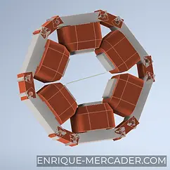
The 3-Phase Squirrel-Cage Induction Motor was a fully student-driven project completed during my Electrical Machines course. The sole objective was to design and build a functional 3-phase AC induction motor capable of running on a 3-phase 48 V AC source. With complete freedom in design and construction, our team chose to create a visually striking educational demonstrator featuring transparent acrylic panels that allow a clear view of the rotor spinning inside the motor during operation.
We designed and built every component from scratch: a custom stator core assembled from precisely cut and varnished transformer steel laminations, hand-wound coils using enameled magnet wire on a custom 3D-printed winding jig, and a squirrel-cage rotor with a modified core and 3D-printed conductive bar adapter. A Wye-Delta starter circuit using digital logic and relays ensured safe startup and smooth operation. The motor achieved reliable sustained no-load running, showcasing the rotating magnetic field in real time through the transparent enclosure.
Developed in equal collaboration with three fellow mechatronics engineering students, this project stands as a tangible demonstration of electromagnetic design, precision fabrication, and hands-on power electronics implementation.

Development Process
1
3D Modeling & Planning
Designed the complete motor in 3D to determine exact dimensions, material quantities, and manufacturing feasibility.

6
Hand-Wound Coils
Wound all stator coils by hand using a custom 3D-printed winding jig for perfect turns and tension.

11
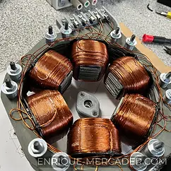
Stator Completion
Final assembly of the stator with all coils secured and wiring routed.

16
Magnet Wire Current Testing
Stress-tested the magnet wire by passing 10 A DC through it to determine its real-world current limit for 208 V operation.

2
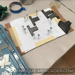
Cutting Transformer Laminations
Precisely cut transformer steel sheets into the custom stator and rotor shapes using the 3D model as reference.

7
Stator Core & Coil Integration
Inserted and secured the hand-wound coils into the assembled stator core.

12
Magnetic Field Validation
Tested the stator’s rotating magnetic field using a free-moving magnet to confirm proper three-phase operation.
18
First Successful Run
Powered up the finished motor and captured it running smoothly under full three-phase operation.

3
Varnish Application
Applied insulating varnish to every individual lamination to prevent eddy currents.
8
Coil Terminal Wiring
Routed and terminated all coil leads for proper three-phase Wye configuration.

13
Rotor Preparation
Recycled and modified an existing rotor, then designed and 3D-printed an iron-filled PLA adapter to mount the squirrel cage bars.
4
Lamination Organization
Applying varnish to each of the laminations

9
Continuity & Resistance Testing
Verified every coil for continuity and measured resistance to ensure balanced windings before final assembly.

14
Squirrel Cage Integration
Installed the custom squirrel cage windings onto the 3D-printed rotor adapter.

5
Stator Core Assembly
Assembled the complete stator core by pressing the individual laminations into a solid, rigid stack.

10
Acrylic Side Panels
Installed transparent acrylic sides to create a fully visible, educational motor housing.

15
Wye-Delta Starter Circuit
Built a Wye-Delta starting circuit on protoboard to safely start the motor at reduced voltage.


